Turbine Flow Meter
- Home
- Measurement Basics
- Turbine Flow Meter
DEPENDABLE FLOW METERS - Turbine Flow Meter

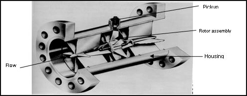
The Turbine flow meter offers accurate and reliable flow measurement. The turbine flow meter consists of the following major components: the turbine housing, shaft, rotor, pickup sensor, and transmitter.
The turbine housing is nothing but a flow tube (pipe) in which a rotor is mounted on a shaft placed along the direction of expected fluid flow. The rotor is a multi-bladed, free spinning impeller which rotates only when the fluid is moving through the pipe. The shaft rests on the internally mounted brackets or supports. These supports perform a dual role of supporting the shaft as well as flow straighteners and stabilizing the flow by minimizing the turbulence. These supports can be fastened by locking clips on either end. A pickup sensor is mounted above the rotor in such a way that it remains out of the flowing stream to avoid contact with the fluid. This maintains the purity of the fluid and protects the sensor from damage. The pickup sensor is essentially a coil of wire closely positioned with a permanent magnet. The figure below explains the construction of a turbine flow meter.

It is important to consider the pressure and temperature conditions and chemical properties of the fluid under measurement while selecting the material of the housing, shaft, rotor, etc. Turbine meter housing is generally manufactured of stainless steel or other metals like bronze, cast iron. They are also available in plastic for some applications. Rotors are often made of stainless steel and bearing use graphite. Other materials like tungsten carbide and ceramics are also used on application requirement. Few special applications use synthetic ruby or sapphire combined with tungsten carbide. The turbine meter shafts and bearings are chosen in such a way that they offer minimum friction to fluid flow and maximum resistance to wear-and-tear as a result of flow velocity. Several types of pickup sensors such as electrical (inductance, capacitance, reluctance, or Hall-effect pickups) or mechanical (gear and magnetic drives) are available in turbine meters.
The rotor mounted on the shaft is in a perpendicular direction to the flow of the stream and possesses a free-running bearing. Its diameter is slightly less than the diameter of the housing chamber. The rotor cannot run on its own, It rotates when the process fluid passes through the pipe and becomes still as soon as flow stops, thus providing an extremely quick response time. Neglecting the frictional effect, the angular velocity of rotation is directly proportional to the fluid flow rate. As the magnetic or stainless steel blades of rotor pass by the pickup sensor, magnetic flux is induced in the coil, generating voltage pulses. When the fluid moves faster more pulses are generated. Therefore, these pulses are proportional to the fluid flow velocity.
Hence, in short, the Flow rate is proportional to the frequency of pulses and Volume is proportional to the total number of pulses. In the form of a mathematical equation this relationship can be expressed as:
f = k*Q
Where,
f = A frequency of pulses generated by pickup sensor ie pulses per second (Hz)
Q = Volumetric flow rate (liters/minute)
k = “K” factor of the turbine meter (pulses per meter)
The transmitter processes these pulses to calculate the fluid flow velocity and volume and then sends it to the controller. The transmitter and pickup sensors have the capability to sense the fluid flow in both the forward and reverse direction..
Turbine meter K-factor: The K-factor of a turbine is the number of pulses produced per unit volume, It varies depending on the meter. It is typically determined by the size (diameter) and type of meter. Ideally, K-factors of similar models are expected to be equal but it is observed that it slightly varies due to manufacturing tolerance. Therefore, before installation, it is essential to calibrate each turbine meter in the factory for the desired fluid measurement. Moreover, K-factor is applicable to only that fluid for which it was calibrated in a factory.
Turbine flow meters are the most commonly used flow meters in various applications such as chemicals, petroleum, and gas, water and wastewater, air, cryogenic liquids, aerospace, pharmaceutical, pulp and paper, metal, mining, and food and beverage industries.
